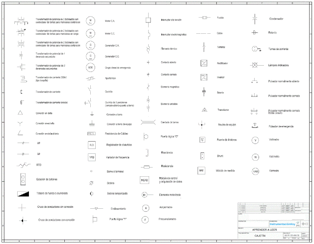
2. SYMBOLOGY LEGEND
3. REPRESENTATION OF ELECTRICAL EQUIPMENT
3.1. Representation of electrical conductors
3.2. Representation of breakers
3.3. Representation of disconnectors
3.4. Representation of other electrical equipments
4. SOME BASIC CONCEPTS
4.1. Difference between disconnectors, contacts and breakers
4.2. Breakers
4.3. Feeder or control device
4.4. Local and remote control
4.5. Automatic or manual
4.6. Electrical protection devices
4.7. Measuring devices
5. MAIN POINTS OF THE GENERAL ELECTRICAL DIAGRAM
5.1. Connection to the mains network
5.2. Substation
5.3. Main Transformer
5.4. Electrical Building
5.5. Electrical cabinets
5.6. Low voltage transformer
5.7. Low voltage distribution cabinet
5.8. MCC
5.9. Essential electrical system
5.10. Safety electrical power
5.10.1. Direct current
5.10.2. Uninterrupted Power System (UPS)
6. REDUNDANT POWER
1. WHAT IS A GENERAL UNIFILAR DIAGRAM?
“The General Unifilar Diagram" indicates the most relevant electrical information in an industrial plant.
This document is under scope of the electrical department, however any instrumentation and control engineer must be able to understand it in order to do his work correctly.
All the electrical conductors (2, 3 or more) are indicated with only one line, and for this reason it is called unifilar diagram.
As a general rule, the unifilar diagram is drawn following the energy flow, from the top down.
Therefore, network connection will be on the top and the final consumers will on the bottom.
It is easy to find electrical symbology normative (for example UNE 606179), nevertheless each project has its peculiarities, so it is more appropriate to check each project symbology.
3. REPRESENTATION OF ELECTRICAL EQUIPMENT
3.2. Representation of breakers
3.3. Representation of disconnectors
3.4. Representation of other electrical equipments
4. SOME BASIC CONCEPTS
4.1. Difference between disconnectors, contactors and breakers
Breaker: Electromechanical equipment is able to maintain or interrupt the electrical current.
The electrical protection is its main function, although it can be used for control functions.
The safety of people and equipment is its main function. Disconnectors are not usually designed to interrupt the electrical current.
Switch disconnector: Electromechanical equipment is able to isolate and interrupt.
Contactor: Electromechanical equipment is able to maintain or interrupt the electrical current.
The control is its main function, these devices are designed to do many operations.
Note: The contactors are usually installed downstream of a breaker.
Note: The contactors are usually installed downstream of a breaker.
Note: Sometimes the contactor isn't installed and a breaker is used directly to control. For example, if a very few operations (open/close) are required, It shouldn't be mandatory to have an electrical contactor.
4.2. Breakers
There are several types of electrical breaker in the industrial plants.
There are simple breakers (like lighting breaker), complex breaker (like the main breaker used to connect with the electrical network), there are single-phase breaker, or three-phase breakers, pressurized with air or pressurized with SF6, oil or vacuum. All these characteristics depend on voltage, technology, age...etc.
The breakers have 2 positions mainly:
- Open (It interrupts the electrical current)
When the breaker is close, the current will be able to go downstream.
Nota: Be careful, if the main breaker is open, downstream equipment could maintain the voltage.
There are several redundant power supply ways in the industrial plants, and some electrical devices can store electrical energy.
Some people that don't take into account this issue die every year.
Therefore, please follow the 5 golden rules to avoid accidents:
There are several redundant power supply ways in the industrial plants, and some electrical devices can store electrical energy.
Some people that don't take into account this issue die every year.
Therefore, please follow the 5 golden rules to avoid accidents:
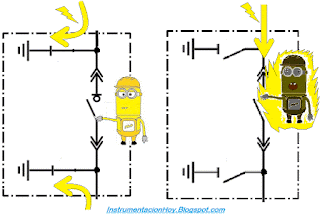
Earthing is necessary for maintenance activities and earthing disconnector are usually used.
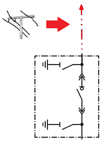
The following picture is the substation unifilar diagram:
It consists of two earthing disconnector and a breaker. If maintenance activities were required (according to the 5 golden rules ), after cut-off, interlocking, verify... the earthing disconnector will be closed (and interlocking) to ensure the safety of people.
If both earthing disconnector are closed, any current leakage will be discharged.
Furthermore , some breakers can be in test mode and/or withdrawal mode
Test mode: The breaker will be opened and it willn't be able to be controlled. Test mode is used to test the signal.
See the withdrawal breaker representation in the following sketch:
Note: Sometimes the electrical devices have mechanically interlocked between themself. A broken line between both devices is used in this case
In the picture, the broken line was indicated that both breaker can't be closed at the same time. But to understand this interlock logic we will check the cabinet wiring diagram.
A feeder device is an equipment that should be always powered.
For example a TV is a feeder.
A TV is usually plugged, and with the remote control can be connected and disconnected.
There are many feeder devices in an industrial plant for example: compressor, computer, HVAC split, etc.
However there are other loads (for example the motor-pumps) that must be controlled, in these cases, open and close the breaker or the contact is required to start and to stop these devices.
4.3. Feeder or control device
A feeder device is an equipment that should be always powered.
For example a TV is a feeder.
A TV is usually plugged, and with the remote control can be connected and disconnected.
There are many feeder devices in an industrial plant for example: compressor, computer, HVAC split, etc.
However there are other loads (for example the motor-pumps) that must be controlled, in these cases, open and close the breaker or the contact is required to start and to stop these devices.
4.4. Local and remote mode
Some electrical loads can be controlled on local mode, on remote mode or both.
For example, some feeder loads breakers can be only actuated on local mode.
On the other hand, for example, some motor-pump can be controlled on remote mode from the main control system (for example a DCS) or on remote mode from the electrical cabinet.
Usually, there is a selector installed in the electrical cabinet to select the remote or local mode.
Therefore, on remote mode: The breaker is in the electrical cabinet (with power supply), but the open and close orders come from a remote device.
Therefore, on remote mode: The breaker is in the electrical cabinet (with power supply), but the open and close orders come from a remote device.
These remote signals (open and close) are usually sent to an auxiliary electrical relay installed in the electrical cabinet. The auxiliary electrical relay will close the main relay which can controls the power supply contactor.
The auxiliary relay and auxiliary contacts are not represented in the general unifilar diagram. If someone wants to see this information, see the cabinets wiring drawings.
4.5. Automatic or manual
4.5. Automatic or manual
The electrical devices can be in automatic or in manual mode.
In manual mode the staff can decide how and when should work the electrical device
In automatic mode the final controller (PLC, DCS, ...) will start and stop the equipment according with its programed logic.
These status Auto./Manual haven't any relation with Local/Remote.
Note: It looks something easy, but a lot of people don't understand the differences between Auto / Manual and Local / Remote.
4.6. Electrical protection devices
Many times, electrical protections are represented in the electrical unifilar diagram.
The electrical protection devices can be integrated in other electrical equipments. For example, many breakers have theirs electrical protections (differential protection, or magneto-thermal protection).
All of these electrical protection could be included in the electrical unifilar diagram.
Others electrical protection devices are carry out by specific equipment, like protection relay.
The protection relay main function is to protect the electrical system.
On the one hand, electrical relays receive signals (voltage value, current, frequency, etc) from measurement instruments. And on the other hand they will send interlock signals to protect others electrical devices.
Each protection functions have a standard code number.
For example:
27- Low voltage
49- High temperature
50- Overcurrent
…etc.
As a general rule, the relays are not represented in the electrical diagram, but the protection function numbers are usually indicated.
50- Overcurrent
…etc.
As a general rule, the relays are not represented in the electrical diagram, but the protection function numbers are usually indicated.
In the previous drawing is represented that the breaker is tripped by a protection relay, with the functions 27, 49 and 50.
Note: As a general rule, the main control system (PLC or a DCS) shouldn't take any electrical protection function. The electrical protections should be managed by specialized electrical system (like the protection relay).
4.7. Measuring devices
The most relevant electrical measuring devices are the voltage transformers and current transformers.
The most relevant electrical measuring devices are the voltage transformers and current transformers.
5. MAIN POINTS OF THE GENERAL ELECTRICAL DIAGRAM
The most relevant electrical devices are represented in the general electrical diagram. If electrical system is big and/or complex, the general electrical diagram could consist of several drawings.
We will be explained the following example:
5.1. Connection to the mains network
Usually, the industrial plants are connected electrical network.
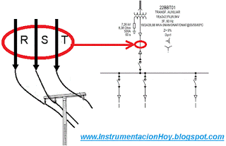
In the example, the electrical connection is represented at the top of the drawing.
In this example, a overhead power line is connected with a small electrical substation.
Usually, the industrial plants are connected electrical network.
In the example, the electrical connection is represented at the top of the drawing.
In this example, a overhead power line is connected with a small electrical substation.
5.2. Substation
The electrical substation is an electrical area, where electrical power is measured, distributed and adapted.
The electrical substation is an electrical area, where electrical power is measured, distributed and adapted.
The electrical substation is installed on the periphery with restricted access.
It will mainly consist of electrical energy measuring equipment, switches, disconnectors, etc.
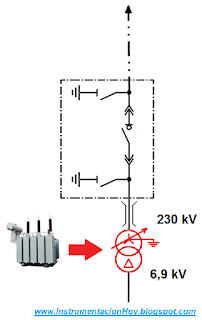
5.3. Main Transformer
In a typical case, the electrical power supply is high voltage value (for example 230kVac).
But, the industrial plant will require a lower values (for example 6,9 kVac), in order to reduce this value a electrical transformer will be installed.
Therefore the main transformer will reduce the voltage value.
5.4. Electrical Building
Following the example, the cable extends from the transformer to the electrical building.
The electrical building is a multi-storey building.
The first floor is "the electrical floor" (with the electrical cabinets).
There are several independent rooms in this floor:
1º- Electrical room where are installed the main electrical cabinets (MCC, medium voltage cabinets, distribution cabinets, etc.)
The second floor is "control floor".
Usually, there are two independent rooms in this floor:
1º- Electronic Room where are installed the control and communication cabinets.
2º- Control Room where are installed the operation stations. The industrial plant will be mainly supervised and controlled from this room.
5.5. Electrical cabinets
Following the diagram, the next electrical devices are the medium voltage cabinets (installed in the electrical room first floor)
Inside of medium voltage cabinets there are the following devices:
1º- The first represented device is the main breaker.
2º- The second device is the low voltage transformer breaker.
3º- The third device is a frequency converter breaker.
5.6. Low voltage transformer
As general rule, low voltage transformer is installed outside the building. This transformer reduces the voltage value from medium voltage to low voltage.
For example from 6,9 kV to 0,48 kV.
As general rule, low voltage transformer is installed outside the building. This transformer reduces the voltage value from medium voltage to low voltage.
For example from 6,9 kV to 0,48 kV.
5.7. Low voltage distribution cabinet
Low voltage transformer powers to low voltage distribution cabinet.
Low voltage transformer powers to low voltage distribution cabinet.
Inside of low voltage distribution cabinet there are the main breaker and several other breakers which power to others low voltage electrical cabinets.
Many electrical low voltage cabinets can be in an industrial plant, but only the most relevant will be represented in the general unifilar diagram.
5.8. MCC
Motor Control Cabinet, is an example of low voltage cabinet.
Motor Control Cabinet, is an example of low voltage cabinet.
These cabinets are splitted in several small cubicles. Each cubicle could contain a breaker, a local/remote selector, push buttons, indicator lamps...
5.9. Essential electrical system
The essential electrical system can independently work in case of power supply fail.
The essential electrical system can independently work in case of power supply fail.
Any electrical loads that must work in case electrical fail are connected to essential system.
Note: Usually, the emergency power generator is installed outside the building.
5.10. Safety electrical power
There are other two systems that could work in case of a power failure in the electrical network. “Direct current system” and the “UPS”.
Both systems are more restrictive than the essential system.
Therefore “Direct current system” and the “UPS” are the safest power systems.
5.10.1. Direct current
This system is powered by the main electrical network through a rectifier.
The rectifier must be installed in power electronics room and It transforms the AC input voltage into DC (For example 125 Vdc)
The rectifier also powers the battery system.
If there was a fail in the electrical network, the battery system will power the direct current system.
Note: Usually, the control electrical devices installed in the medium voltage cabinets are powered by the direct current system.
For example in the following drawing, an auxiliary relay is used to control the breaker, this relay will be powered with direct current.
5.10.2. Uninterrupted Power System (UPS)
Uninterruptible Power Supply (UPS) meet a similar function, but it is an alternating current.
Uninterruptible Power Supply (UPS) meet a similar function, but it is an alternating current.
Usually, this system is redundant powered.
One from direct current system through an inverter and the other from the essential system.
One from direct current system through an inverter and the other from the essential system.
6. REDUNDANT POWER
Redundant power supply increases the availability of the electrical system. Lately, It is very common requirement in all industrial project.
Redundant power supply implies that there are two way to power the electrical devices.
In the following example there are four devices:
- Two main breakers (1 and 2)
- Coupler breaker (3).
- Automatic Transfer System (ATS) (4)
Usually, each bus power theirs loads from theirs main breakers, meanwhile the coupler breaker is open.
If the ATS detect a fail in one side It will open the main breaker (1) (which had a fail) and It will be closed the coupler breaker (3).
Note: ATS Automatic Transfer Switch can be an specific electrical device, but sometimes It is used the main control system.
Thanks to Mr. Javier Iglesias for those clarifications
By: Julio.C Fernández Losa 06/01/2017
Contac us: InstrumentacionHoy@gmail.com










Thanks For Sharing This Informative Article.
ReplyDeletep and id