1. WHAT IS AN ISOMETRIC PIPING DRAWINGS?
2. ISOMETRIC VALUE
3. ISOMETRIC PARTS
3.1 Title block
3.2 The pipe design
3.3 Material List
4. INTRUMENT DEPARTAMENT SCOPE
3.2 The pipe design
3.3 Material List
4. INTRUMENT DEPARTAMENT SCOPE
--------------------
Note: The P&IDs are useful documents to undestand the process and to check the general characteristics of the pipes, instruments, valves and others devices. But we can not know the plant design. To know the pipe actually designed (form, lenght, size, ...) It is necesary to check the isometric piping drawings.
1. WHAT IS AN ISOMETRIC PIPING DRAWINGS?
The isometric drawings are a group of documents (tens or hundreds) that are used to design pipe system in an industrial plant.
2. ISOMETRIC VALUE
The isometrics are the most relevants document in piping department.
These documents define the piping material list, and they can be a bottleneck in any project. Also, mistakes in this document could imply high costs.
The pipe design is afected by the instrument and valves requirement, therefore, instrument department should give support to revise the isometric drawing.
The pipe design is afected by the instrument and valves requirement, therefore, instrument department should give support to revise the isometric drawing.
3. ISOMETRIC PARTS
3.1 Title block
Isometric drawing must have a standard title-block as other project oficial drawings.
- Pipe code. Each pipe will be coded and included in the isometric drawings. For example: "04LBB20BR0101"
- Page number and total page used to represent all the pipe. For example: "4 of 4"
- Pipe design conditions. For example: "568ºC / 36,2bar g"
- Pipe Specification For example: "E340"
- Pipe diameter. For example " 22" ".
- Revision. For example " 2-For construction".
- People in charge of document (Client, engineering, promoter, etc...)
-Project name
-Project system
3.2 The pipe design
The document main part is the pipe drawing.
In the drawing is indicated:
- Dimensions
- Relative coordinates
- Areas with insulation or traced areas
- Location of supports
- Orientation
- Required angles
-Etc..
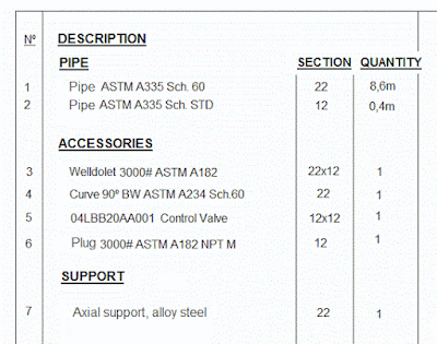
3.3 Material List
In the list is indicated:
- Description
- Quantity
- Material
- Thickness
-Etc..
4. INTRUMENT DEPARTAMENT SCOPE
Usually, there are fewer human resources in each project, therefore is very little time to revise isometric diagrams. But there are some minimun points that we recommend to check and coordinate with pipe department:
- Locate and design the instrument connection
- Valve layout and connection


I have read this article and i come to understand very easily.
ReplyDeletewww.sonusinghyoutube.com
ReplyDeleteThanks For Sharing This Informative Article.
p and id7