Note: We should like to thank the technical clarifications of Pilar Naranjo and Ángel Arranz in this post.
----------------------------------
1. INTRODUCTION
1.1. What is a Control Valve?
1.1.1. Modulating Control Valves
1.1.2. On-off Control Valves
2. BASIC ACCESSORIES FOR THE PNEUMATIC CONTROL OF A VALVE
2.1. Pneumatic positioner
2.2. Pneumatic actuator
2.3. Solenoid Valve
2.4. Pneumatic pilot
2.5. Air pressure regulator and filter
2.6. Check valve
2.7. Vessel tank
2.8. Booster
2.9. Quick Exhaust
2.10. Flow regulator
2.11. Emergency push button
3. SPECIFY A SOLENOID VALVES
3.1. According to how they are actuated
3.2. According to control mode
3.3. According to the installation
3.4. According to the resting position
3.5. According to power supply
3.6. According to number of ways
3.7. Other considerations
4. FAIL VALVE TYPES
4.1. What is FC, FO or FL?
4.2. Spring installation in globe valves
5. ON-OFF VALVE PNEUMATIC SKETCH
5.1. On-off valve pneumatic sketch example (single acting with 3/2 solenoid valve)
5.2. On-off valve pneumatic sketch example (single acting with 3/2 solenoid valve and quick exhaust)
5.3. On-off valve pneumatic sketch example (single acting with 3/2 solenoid valve and flow regulator)
5.4. On-off valve pneumatic sketch example (double acting with 5/2 solenoid valve)
5.5. On-off valve pneumatic sketch example (double acting with two 3/2 solenoid valves and a 5/3 air piloted pneumatic valve)
5.6. On-off valve pneumatic sketch example (double acting with a 5/2 solenoid valve, two 3/2 air piloted pneumatic valves and a vessel air tank)
6. MODULATING CONTROL VALVES PNEUMATIC SKETCH
6.1. Single acting control valve example
6.2. Single acting control valve example and solenoid override valve
6.3. Single acting control valve example and booster
6.4. Double acting control valve example and vessel air tank
6.5. Double acting control valve example
6.6. Double acting control valve example with vessel tank, booster, override solenoid valve
----------------------------------
1. INTRODUCTION
Usually, the "control valves" are the final elements whose keep the process stably.
In this post, we are going to explain the main points regarding to valve pneumatic sketches.
In the first part, it will be indicated the main pneumatic accessories and in the second part pneumatic sketch will be explained.
1.1. What is a Control Valve?
It might be said that "Control Valves" are the valves which are controlled by external signals.
They could be separated in two groups:
- Modulating Control Valves
- On-off Control Valves
1.1.1. Modulating Control Valves
"Modulating Control Valves" are commonly called "Control Valves"
These valves can vary the size of the flow passage and this enables the continuous control of flow rate.
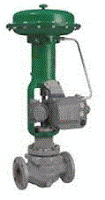
The most used valves in this application are the globe valves, and to a lesser degree the V-Ball, rotary plug, triple offset butterfly, ...
1.1.2. On-off Control Valves
"On-Off Control Valves" are commonly called "On-Off Valves"
These valves can't vary the size of the flow passage, they can only establish two status (open or close is a discrete control).
The most used valves in this application are the ball valves, butterfly, gate, ...
A special case of on-off control valve is when it is used to keep a certain operating point, for example an enthalpy balance in a process system.
In this case there is a calculated Cv that the valve should keep. A travel stop is required to keep this Cv value.
Therefore the process department should indicate the pressure drop, the flow, temperature, etc...
Note: The "Cv" is a ratio which indicates the hole size that is required.
Usually the globe valves (with linear characteristic and 70% in the normal flow) are used in this application.
Other on-off valve special application is the intermediate positions valves. These valves can vary the size of the flow passage but the continuous control of flow rate is not required (therefore are not consider like Modulating Control Valves). In this case, the positioner and actuator requirements are less severe.
2. BASIC ACCESSORIES FOR THE PNEUMATIC CONTROL OF A VALVE
2.1. Pneumatic positioner
The pneumatic positioner is charge of establishing the valve position
Usually, the control system will send a electrical signal (for example: 4-20mA) to pneumatic positioner.
The pneumatic positioner knows the valve position and it will adjust the air flow which is sent to the valve pneumatic actuator to get the required position by the control system.
2.2. Pneumatic actuator
The pneumatic actuator is charge of transforming the pneumatic energy in mechanical energy which will be used to move the valve plug.
They could be divided in two groups:
- Linear or rotary actuators (depending on
- Single acting or double acting actuators
1º- Linear or rotary actuators
a) Linear
The linear actuators are installed in valves with linear movement. For example: globe valves.
Note: Usually the control valves require linear actuators
The most common linear actuators are diaphragm or piston:
b) Rotary
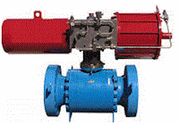
The rotary actuators are installed in valves with rotary movement. For example: ball valves.
Butterfly valve, ball valve, V-ball valve, plug valve, ... are some rotary valves examples
Usually they require 90º of rotation to open or close.
"Diaphragm or piston" actuators are used for "Control Valves" applications. These actuators are adapted to transform the linear movement into rotational movement.
"Rack & Pinion or Scotch Yoke" are used for "On-Off Valves" applications.
2º "Single acting" or "double acting"
Linear actuators or rotary actuators can be single or double acting.
c) Single acting
The working fluid acts on one side of the piston only. If a certain pressure value is not overcome in this side, the spring will move the piston to the initial position.
d) Double acting
The working fluid acts on both side of the piston.
2.3. Solenoid Valve
It is an on-off valve controlled by an electrical solenoid.
When the solenoid is powered, a magnetic field is generated and it will move a mechanical element, changing the valve position.
Usually these valves are used to control bigger on-off valves (like the following picture).
Also, they can be directly installed in process line with small size pipes (For example <1")
Note: Sometimes, solenoid valves are installed in modulating control valves. In these applications the solenoid usually overrides the pneumatic positioner and forces the valve to fail position (It is related to safety actions).
2.4. Pneumatic pilot
It is a small valve controlled by air.
Pneumatic pilots are installed pneumatic sketch when they are required.
Note: We will show some examples in this post.
2.5. Air pressure regulator and filter
This equipment is usually required by client specifications.
This equipment allows us:
1º- Limit the control pressure that we supply to the valve
2º- Remove the suspended particles.
3º- Purge the water (manual or automatic)
2.6. Check valve
The check valve allows flow in one direction and automatically prevents back flow (reverse flow) when fluid in the line reverses direction.
2.7. Vessel tank
Vessel tank is an air-pressure storage tank.
It is installed if valve must be operated in case of air fail.
For example if the valve is "fail close" or "fail open" and there is a double acting actuator installed.
2.8. Booster
The "booster" is a pneumatic amplifier, it is usually installed when a high flow is required in the pneumatic actuator.
Booster types:
- Proportional (1:1)
- Amplifiers or multipliers (1:2 , 1:4 , 1:6 , 1:8 , ...)
- Reducers (2:1 , 4:1 , 6:1 , 8:1 , ...)
The boosters have 2 inputs and 1 output. One input will be the main air flow and the second one will be pneumatic pilot. Pneumatic pilot function is to regulate the air output flow.
The booster more used is the proportional (1:1).
This mean the pressures in the output and in the input are the same, but the output flow is bigger.
P1 = P2 < P3
Q2 > Q1
Q2=Q1+Q3
2.9. Quick Exhaust
"Quick Exhaust", as its name suggests, this equipment offers a greater air transport capacity when the actuator is venting the air.
"Quick Exhaust" will be usually installed with on-off valves if a smaller stroke time is required.
2.10. Flow regulator
This device allows to adjust manually the air flow, in both direction.
"Flow regulator" will be usually installed with on-off valves if to adjust the stroke time is required.
For example, to increase the stroke time to avoid a water hammer.
2.11. Emergency push button
Pneumatic and electric push button.
This mechanical accessory allows to the staff control directly and locally the valve.
.
For example, it can be used for the "partial stroke" test.
3. SPECIFY A SOLENOID VALVES
Some considerations for specify a solenoid valve are given below.
3.1. According to how they are actuated
- Direct acting solenoid valves: Current through the coil generates a enough force to move the valve.
- Pilot operated solenoid valves: Current through the coil doesn't generate an enough force to move the valve also a minimum air pressure value is required.
The pilot (external or internal) will use this minimum air pressure and the current required to move the valve.
For example in the following picture there are 2 different data sheets.
The first valve is a "direct acting solenoid valve" because it can work with a pressure range from "0 bar" to "10bar".
The second one is a "pilot operated solenoid valve" because it requires a minimum air pressure of 2 bar.
To select "direct acting solenoid valve" or "pilot operated solenoid valve" is related to power consumption. It is easier to find low powered "pilot operated solenoid valve" (<2W) than a low powered "Direct acting solenoid valve".
This point is easy to understand because the "pilot operated solenoid valve" will use the electrical power and air pressure.
Note: If a solenoid valve is installed with a positioner (override), it is recommended "direct acting solenoid valve"
3.2. According to control mode
- Conventional: The solenoid valve is controlled exclusively by electrical signals.
- Manual reset: There are several types of manual reset (No Voltage Release, Electrically Tripped). The most common are the "No Voltage Release".
In this model if the solenoid valve is energized valve (in working mode), when the voltage is lost, it will change and it will be locked.
Voltage and manual reset will be required to return the solenoid valve to its working mode.
- Manual override: In addition to the control through the electrical signal, the solenoids can be mechanically driven by a local button..
3.3. According to the installation
- Solenoid valves that will be in contact with process fluid. These solenoid valves will installed directly in the process line (usually tubing).
-Solenoid valves for actuators piloting (the fluid will usually be air). The assembly can be direct on the actuator without additional tubing,
3.4. According to the resting position
- Mono-stable: These types of valves have a single stable position, in which they will be placed when they are not activated by any external signal. The stable position is due to the action of one or several springs.
For example:
- Bi-stable: These type of valves do not have a defined rest position. Theirs position depends on the last signal that has been activated. These valves do not have springs.
For example (5/2 Solenoid valve):
3.5. According to power supply
A solenoid valve can be:
- Direct current or alternating current (DC or AC). The frencuency should be specified in AC mode.
- Voltage level (for example: 24V, 110V o 220V...).
- Power consumption (for example: low power <2W).
Note: Lower power can be a requirement by the client and it can help to install lower section cables.
3.6. According to number of ways
-2/2: 2 ways 2 positions
For example:
-3/2: 3 ways 2 positions
For example:
The following sketches are not bidirectional (3/2NC o NA)
-5/2: 5 ways 2 positions
For example:
-5/3: 5 ways 3 positions.
For example:
According to this last pneumatic sketch, this solenoid valve will maintain the position in case of electrical fail.
On the other hand according to the following sketch, the valve will maintain the air blocked in case of electrical fail.
3.7. Other considerations
- Enclosure protection: IP (International normative) or NEMA (EE.UU normative)
- Electrical certification required in hazardous areas: Explosion proof, intrinsically safe... Normative: IEC, ATEX, FM…(International, Europe, EE.UU...)
- SIL required.
- Body material.
- Gaskets (according to design temperature and fluid characteristics).
- Coil insulation class. If the temperature is high is recommended class type H
4. FAIL VALVE TYPES
4.1. What is FC, FO or FL?
Air fail and the electrical fail position must be indicated in the data sheet when a fail position is required.
Usually electrical fail and air fail should maintain the same fail position.
FC -> "Fail Close" -> An electrical fail or an air fail will position the valve in closed status.
FO -> "Fail Open" -> An electrical fail or an air fail will position the valve in opened status.
FL -> "Fail Last" -> An electrical fail or an air fail will maintain the valve in the same position.
Note: Usually in on-off valves applications, single acting actuators are installed in fail close and fail open. And double acting are usually installed in fail last application.
However, to select single acting or double acting in modulating control valves depend more on the force required to move the valve (size, shutoff pressure, model)
Therefore the following points should considered if fail last (FL) is required and a single acting actuator is installed or if FO or FC is required and a double acting actuator is installed
- If a single acting actuator is installed and fail last (FL) is required, it should be also indicated "drift to close "or "drift to open" (trying to define where the spring should be installed).
For example: The tempering control valve installed with the high pressure turbine by-pass.
A heat exchanger will be usually installed downstream, and after that there will be a medium pressure steam turbine.
"Fail Last" and "Drift to Open" is usually required for this application.
"Fail Last" means that if there is a temporary problem, it is better to maintain the same valve position.
(If the valve was completely open, water could came into the steam turbine and if the valve was completely close heat exchanger could be burned)
"Drift to Open" means that if the fail is not temporary and the actuator lost little by little all the air, to protect the heat exchanger is more important (Steam turbine has its own protection system).
- If a double acting actuator is installed and fail close or fail open is required, a vessel air tank is necessary to move the valve in case of air fail.
Note: If there is a electrical fail in a modulating control valves positioner with single acting actuators and fail open or fail close is required, the actuator air will be vented by the positioner (if the positioner configuration is correct).
However in many cases, the positioner will not be able to go to safe position in double acting actuator in case of electrical fail.
In these cases can be installed an special card in the control system and solenoid valve in override.
The card will detect the fail and it will trip the solenoid.
4.2. Spring installation in globe valves
The spring installation depends on the following considerations:
1º- If the valve "Push Down To Open" (PDTO) o "Push Down To Close" (PDTC)
2º- if fail open is required (FO) or if fail close is required (FC)-
According with both points:
Note: The globe valve will usually be push down to close "PDTC".
Note: The electronic positioners have a software option to configure that if to open more the valve is required it will supply more or less air.
It is preferable to use this positioner software option in order to get always:
4mA - 0%
20ma --> 100%
5. ON-OFF VALVE PNEUMATIC SKETCH
5.1. On-off valve pneumatic sketch example (single acting with 3/2 solenoid valve)
This sketch could apply to fail close or fail open valve.
5.2. On-off valve pneumatic sketch example (single acting with 3/2 solenoid valve and quick exhaust)
This sketch could apply to fail close or fail open valve.
Note: The quick exhaust tries to get a quickest action with the spring actuation.
5.3. On-off valve pneumatic sketch example (single acting with 3/2 solenoid valve and flow regulator)
This sketch could apply to fail close or fail open valve.
Note: According with the sketch, the flow regulation tries to reduce the flow (velocity) action with the piston pressurization.
5.4. On-off valve pneumatic sketch example (double acting with 5/2 solenoid valve)
This sketch could apply to fail last valve.
Note: During a fail case piston chamber must remain pressurized, therefore a check valve is required.
5.5. On-off valve pneumatic sketch example (double acting with two 3/2 solenoid valves and a 5/3 air piloted pneumatic valve)
The following sketch is similar to the previous example but in this example has been given a special importance to keep the piston pressurized (it is safer than to use the check valves).
Note: A similar sketch is used in some lifting platforms.
5.6. On-off valve pneumatic sketch example (double acting with a 5/2 solenoid valve, two 3/2 air piloted pneumatic valves and a vessel air tank)
This sketch could apply to fail close or fail open valve.
Note: For this same example some suppliers use one 6/2 air piloted pneumatic valve instead of two 3/2 pneumatic valves.
6. MODULATING CONTROL VALVES PNEUMATIC SKETCH
6.1. Single acting control valve example
This sketch could apply to fail close or fail open valve.
6.2. Single acting control valve example and solenoid override solenoid valve
This sketch could apply to fail close or fail open valve.
6.3. Single acting control valve example and booster
This sketch could apply to fail close or fail open valve.
6.4. Double acting control valve example and vessel air tank
This sketch could apply to fail close or fail open valve.
Note: If a handwheel is required, a manual by-pass valve can be installed between both pneumatic chambers with the double acting control valve, as it's indicated in the following example.
This manual valve must be opened before using the handwheel.
6.5. Double acting control valve example
This sketch could apply to fail last valve.
6.6. Double acting control valve example with vessel tank, booster, override solenoid valve
This sketch could apply to fail close or fail open valve.
By: Julio.C Fernández Losa 24/09/2015
In collaboration with: Pilar Naranjo and Ángel Arranz


